| |
|
|
| |
|
|
| |
|
|
|
|
|
|
|
|
|
|
|
|
|
|
|
|
|
|
|
|
|
Accessories |
|
|
|
|
|
Adapters
|
|
|
|
|
|
ISA-PC/104
adapter
|
|
|
|
|
|
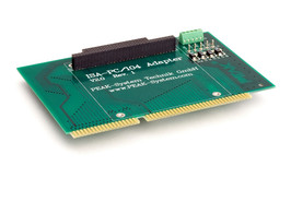
These adapters can
be used to fit and operate PC/104 cards in PCs with ISA slots.
Multiple
cards can be stacked together on a single adapter.
There are screw
terminal adapters which allow the different power supply voltages (+5
V,
-5 V, +12 V, -12 V) to be accessed on the card. Four control LEDs show
the relevant status. A stack-through connector is provided for the
PC/104 bus.
|
|
 |
|
|
|
|
|
|
|
| |
|
|
|
|
|
|
|
|
|
|
|
|
PCI-PC/104-Plus
Adapter
|
|
|
|
|
|
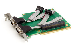
| These adapters can
be used to fit and operate PC/104-Plus cards in PCs with PCI slots.
Multiple cards can be stacked together on a single adapter. |
|
|
|
|
|
|
|
|
|
| |
|
|
|
|
|
|
|
|
|
|
|
|
PCI-Express-PCIe/104
Adapter
|
|
|
|
|
|
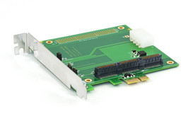
This adapter can be
used to fit and operate PCI/104-Express cards in PCs with PCI Express
slots. Multiple cards can be stacked together on a single adapter.
The adapter has its own internal voltage controller which generates
the
5-Volt supply for the PCI/104-Express card from the 12 Volts from the
PC
PCI Express slot. As an option, the 5-Volt supply can be connected
directly via the HD connection. All supply voltages are visualized by
LEDs and can be separated with jumpers in order to do current
measurement.
|
|
|
|
|
|
|
|
|
|
| |
|
|
|
|
|
|
|
|
|
|
|
|
PCIe-miniPCIe
Adapter
|
|
|
|
|
|
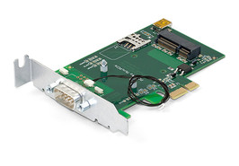
With the help of
the PCIe-miniPCIe adapter, you can operate PCI Express Mini and Half
PCI
Express Mini cards in a computer with low profile housing. Two spacers
on the plug-in card can be appropriately positioned to attach the card
in place. The adapter includes a Mini-USB socket, a Micro-SIM card
holder, as well as a voltage supply of 1.5 V and 3.3 V for plugged PCI
Express Mini cards.
In addition to the PCAN-miniPCIe from PEAK-System, USB solutions
as well as cards for wireless communications
such as WLAN, WWAN, and WPAN can be operated via the adapter.
|
|
 |
|
|
|
|
|
|
|
| |
|
|
|
|
|
|
|
|
|
|
|
|
PCAN-Term
|
|
|
|
|
|
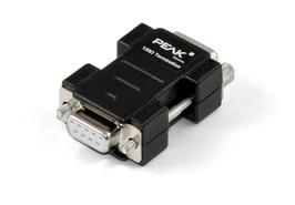
High-speed CAN
busses (ISO 11898-2) must be terminated at their ends by
resistors.
The adapters PCAN-Term and PCAN-MiniTerm are used if no CAN node or a
CAN node without internal termination is connected at these
points.
The termination adapters can also be used for CAN FD busses.
|
|
|
|
|
|
|
|
|
|
| |
|
|
|
|
|
|
|
|
|
|
|
|
PCAN-T-Adapter
|
|
|
|
|
|
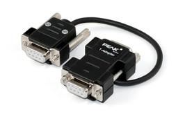
| The
PCAN-T adapter makes a tap of the data lines and the ground within a
CAN bus in order to connect a CAN node.The
CAN node is not terminated in this case.
|
|
|
|
|
|
|
|
|
|
| |
|
|
|
|
|
|
|
|
|
|
|
|
|
|
|
PCAN-D
Sub Connection Adapter
|
|
|
|
|
|
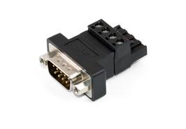
CAN hardware from PEAK
system has a 4-pin screw terminal block as CAN connection for versions
in the DIN rail housing.�
The PCAN-D-Sub connector adapts its pin assignment to a 9-pin D-Sub
connector.�This makes it possible, for example, to connect our
standard CAN cables and to connect the
device to one of our CAN-PC interfaces.�
The PCAN-D-Sub connection adapter can be used in CAN-FD buses.
|
|
|
|
|
|
|
|
|
|
| |
|
|
|
|
|
|
|
|
|
|
|
|
Cables
|
|
| |
|
|
|
PCAN-Cable 1 & 2
|
|
|
|
|
|
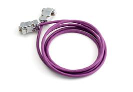
These cables are
needed to set up a CAN bus and are specially designed to be used in a
CAN environment. If two
High-speed CAN hubs need a simple direct connection between them, the
PCAN-Cable 2 with integrated termination can be used. The PCAN-Cable 1
is suitable for putting
together a CAN bus which shall contain tap connections and separate
termination (PCAN-T-Adapter and PCAN-Term products).
The cables can also be used in CAN-FD buses.
|
|
|
|
|
|
|
|
|
|
| |
|
|
|
|
|
|
|
|
| |
|
|
|
PCAN-Cable 3
|
|
|
|
|
|
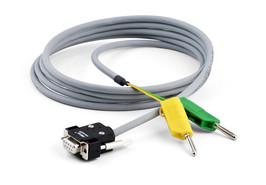
With this
cable the two components CAN-High and CAN-Low of the differential CAN
signal can be picked up from a CAN bus or directly from a CAN
interface.
An easy connection to test and measurement setups is accomplished by
the
banana plugs.
The PCAN-Cable 3 can also be used for CAN FD busses.
|
|
|
|
|
|
|
|
|
|
| |
|
|
|
|
|
|
|
|
| |
|
|
|
LIN
Connection Cable for PCAN-LIN
|
|
|
|
|
|
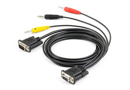
On the PCAN-LIN
module, the field busses and the power supply are
connected together via a D-Sub plug. However, for some applications a
separate access to the LIN components is necessary.
The LIN
connection cable for PCAN-LIN allows the tapping of individual lines.
The LIN and the supply lines are lead directly out to separate plugs
and
the CAN lines are forwarded to a D-Sub plug.
The connection cable can be used without problems for CAN FD busses.
|
|
|
|
|
|
|
|
|
|
| |
|
|
|
|
|
|
|
|
|
|
|
|
LIN
Connection Cable for PC LIN Interfaces
|
|
|
|
|
|
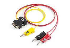
The PLIN-USB
adapter is connected to the LIN bus via D-Sub. On the adapters
PCAN-USB
Pro FD and PCAN-USB Pro, the two field busses CAN and LIN are
connected
together via a D-Sub plug. However, a separate access to the LIN
components is necessary.
The LIN Connection Cable for PC LIN Interfaces allows
the tapping of individual lines. The LIN and the supply
lines are lead directly out to separate plugs and the CAN
lines are forwarded to a D-Sub plug.
The connection cable can be used without problems for
CAN FD busses.
|
|
|
|
|
|
|
|
|
|
| |
|
|
|
|
|
|
|
|
|
|
|
|
PCAN-Cable OBD
2
|
|
|
|
|
|
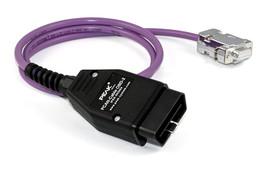
| Many modern motor
vehicles have the OBD-2 interface for the connection of various
diagnostic and test devices. The contained CAN cables can be
accessed
using this adapter cable. |
|
|
|
|
|
|
|
|
|
| |
|
|
| |
|
|
|
|
|
|
|
|
|
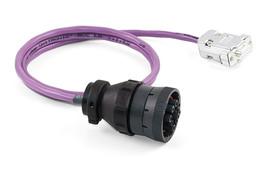
PlotPCAN-Cable
J1939
|
|
|
|
|
|
The SAE J1939 protocol
establishes consistent CAN messages for the communication and
diagnosis between components of heavy-duty
vehicles such as construction machinery, tractors, and agricultural
machines. In this area, robust DEUTSCH connectors are often used for
on-board diagnostics connection.
The PCAN-Cable J1939 routes the CAN lines of those connections to a
D-Sub socket, thus allowing access to PEAK CAN interfaces.
|
|
 |
|
|
|
|
|
|
|
| |
|
|
| |
|
|