| |
|
|
| |
|
|
| |
|
|
|
|
|
|
|
|
|
|
|
|
|
|
|
|
|
|
|
|
|
PC CAN
Softwares |
|
|
|
|
|
Development Packages
|
|
|
|
|
|
PCAN-Basic
|
|
|
|
|
|
The
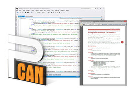
PCAN-Basic API (application programming interface)
allows easy development of powerful software with CAN and CAN FD
support. It includes all of the functions that an application needs in
order to communicate with PCAN PC hardware. The cross-operating-system
design makes it possible to easily port software projects between
platforms.
PCAN-Basic consists of the actual device driver and
an
interface DLL, which provides the API functions. |
|
|
|
|
|
|
|
|
|
| |
|
|
|
|
|
|
|
|
|
|
|
|
PCAN-Developer
4
|
|
|
|
|
|
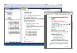
The
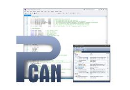
professional programming interface PCAN-API of the PCAN-Developer
package makes it possible to create complex Windows� applications with
CAN and CAN FD support. The API (Application Programming Interface)
provides an extensive function library using interface DLLs for 32-bit
and 64-bit systems.
Unlike PCAN-Basic, the CAN communication is handled by Clients and
offers significant advantages. Thus, not only a single but multiple
applications can access a physical CAN channel. Furthermore, it works
even without hardware: Via virtual connections, Clients establish a
simulated CAN communication among Windows� applications.
|
|
|
|
|
|
|
|
|
|
| |
|
|
|
|
|
|
|
|
|
|
|
|
PCAN-RP1210 API
|
|
|
|
|
|
The Recommended
Practice 1210 was defined by the Technology and Maintenance Council
(TMC)
as a standardized API for communication between Windows� applications
and communication networks in vehicles.
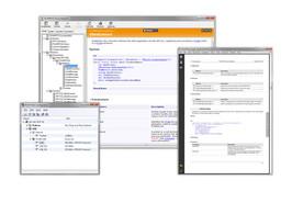
The PCAN-RP1210 API by
PEAK-System is an implementation of the RP1210 versions A and C with
support for CAN and SAE J1939 networks. Thus, the API makes it
possible
to develop own RP1210 applications and to use already existing ones
with
CAN interfaces by PEAK-System.
|
|
|
|
|
|
|
|
|
|
| |
|
|
|
|
|
|
|
|
|
|
|
|
PCAN-CCP API
|
|
|
|
|
|
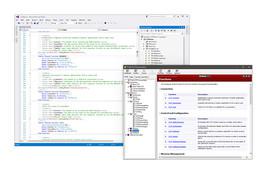
The PCAN-CCP
API is a programming interface for the
communication between Windows� applications (Masters) and electronic
control units (Slave ECUs). The API is based on the CAN Calibration
Protocol (CCP) by ASAM and is mainly deployed for development in the
automotive area. The PCAN-CCP API uses the CAN bus as transmission
medium.
For accessing the CAN hardware in the computer, PCAN-CCP utilizes the
programming interface PCAN-Basic, which is part of the scope of supply
of every CAN interface from PEAK-System. The PCAN-CCP API package is
available free of charge.
|
|
|
|
|
|
|
|
|
|
| |
|
|
|
|
|
|
|
|
|
|
|
|
PCAN-XCP API
|
|
|
|
|
|
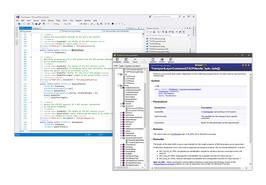
The PCAN-XCP API is a
programming interface for the
communication between Windows� applications (Masters) and electronic
control units (Slave ECUs). The Universal Measurement and Calibration
Protocol (XCP) is a further development of the CAN Calibration
Protocol
(CCP) by ASAM. XCP supports multiple transmission mediums, but is not
compatible to CCP.
For accessing the CAN hardware in the computer, PCAN-XCP utilizes the
programming interface PCAN-Basic, which is part of the scope of supply
of every CAN interface from PEAK-System. The PCAN-XCP API package is
available free of charge.
|
|
|
|
|
|
|
|
|
|
| |
|
|
|
|
|
|
|
|
|
|
|
|
PCAN-PassThru
API
|
|
|
|
|
|
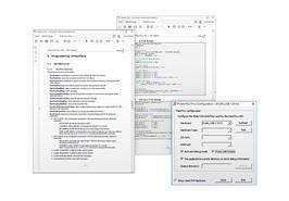
For the programming of
control units (ECU), there are countless
applications from various manufacturers which are used in the
development and diagnosis of vehicle electronics. The interface for
the
communication between these applications and the control units is
defined by the international standard SAE J2534 (Pass-Thru). Thus, the
hardware for the connection to the control unit can be selected
regardless of its manufacturer.
PCAN-PassThru allows the use of SAE J2534-based applications with CAN
adapters from PEAK-System.
|
|
|
|
|
|
|
|
|
|
| |
|
|
|
|
|
|
|
|
|
|
|
|
PCAN-ISO-TP API
|
|
|
|
|
|
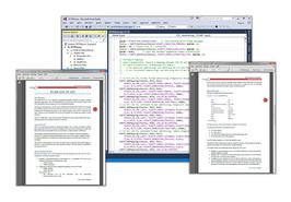
ISO-TP (ISO 15765-2)
is an international standard for the transfer of
data packages via CAN. Above CAN (OSI layers 1 and 2), the protocol
covers the OSI layers 3 (Network Layer) and 4 (Transport Layer). It
can
transmit data packages of up to 4095 bytes per CAN message. The data
bytes are transmitted segmented with multiple CAN frames.
The PCAN-ISO-TP API implements the functionality of the standard on
the
basis of 10 functions. They are categorized in Allocation,
Configuration, Address Mapping Configuration, Information, and
Communication.
PCAN-ISO-TP uses the PCAN-Basic programming interface to access the
CAN
hardware in the computer. PCAN-Basic is supplied with each CAN
interface
of PEAK-System.
|
|
|
|
|
|
|
|
|
|
| |
|
|
|
|
|
|
|
|
|
|
|
|
PCAN-UDS API
|
|
|
|
|
|
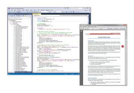
UDS (ISO
14229-1) stands for Unified Diagnostic Services and defines
the communication with control units (ECUs). The Windows� software
tests
the controller using various services. The process is done on the
client-server principle where the program is in the position of the
client (also called tester). UDS uses the ISO-TP standard as transport
protocol, thus UDS can transmit data blocks of up to 4095 bytes size.
Besides the exchange of maintenance information, for example, the
transfer of firmware is possible.
The PCAN-UDS API implements the functionality of the standard on the
basis of 8 functions. They are categorized in Tester Allocation,
Configuration, Information, Utilities, Services, and Communication.
|
|
|
|
|
|
|
|
|
|
| |
|
|
|
|
|
|
|
|
|
|
|
|
PCAN-OBD-2 API
|
|
|
|
|
|
For on-board
diagnostics, the OBD-2 standard defines the
exchange of specific vehicle parameters. The client makes a request on
the connected control units (ECUs) in the vehicle to which one or
several ECUs are answering. As part of OBD-2, the ISO 15765-4 standard
describes the CAN bus as a transmission option.
The PCAN-OBD-2 API implements the functionality of the standard on the
basis of 15 functions. They are categorized in Tester Allocation,
Configuration, Information, Services, and Communication.
According to ISO 15765-4, OBD-2 is based on UDS. Analog to this,
PCAN-OBD-2 uses the PCAN-UDS programming interface for the exchange of
diagnostic data.
|
|
|
|
|
|
|
|
|
|
| |
|
|
|
|
|
|
|
|
|
|
|
|
PLIN-API
|
|
|
|
|
|
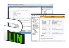
LIN (Local
Interconnect Network) is a serial network protocol which
is characterized by a master-slave architecture and transmission
patterns. The master regulates the bus access and controls the
communication of up to 16 participants. Only when the master prompts a
slave, the latter is allowed to transmit its stored information. On
each
request of the master, answers defined within a schedule table follow
in
a fixed time sequence.
LIN was introduced by five automobile manufacturers in 1999 and
further
developed under the supervision of the LIN Consortium. Until today,
the
LIN bus has proven itself to be a cost-effective alternative to the
CAN
bus for networking sensors and actuators in vehicles, such as seat,
door, mirror, and climate controls.
|
|
|
|
|
|
|
|
|
|
| |
|
|
|
|
|
|
|
|
|
|
|
|
LabVIEW Driver
|
|
|
|
|
|
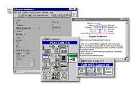
| The LabVIEW
drivers from KDI - Kunze Digital
Instrumentation support the development environments PCAN-Basic and
PCAN-Developer. |
|
|
|
|
|
|
|
|
|
| |
|
|
|
|
|
|
|
|
|
|
|
|
PC Software
|
|
|
|
|
|
PCAN-View
|
|
|
|
|
|
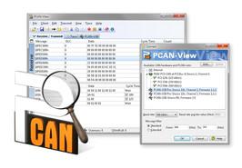
The software PCAN-View
for Windows� is a simple CAN monitor for viewing, transmitting, and
recording CAN data traffic.
Messages can be transmitted manually and periodically at a
user-determined bit rate. Bus system errors and memory overflows in
the CAN hardware are displayed during the
process. The trace function can be used to record and save CAN data
traffic.
PCAN-View is supplied with every PCAN PC hardware product and allows a
quick and easy start. All available PEAK CAN interfaces are listed in
the connection dialog. After
selecting the hardware and the bit rate, the user can access all the
software functions, hardware-specific settings, and information.
|
|
|
|
|
|
|
|
|
|
| |
|
|
|
|
|
|
|
|
|
|
|
|
PLIN-View
Pro
|
|
|
|
|
|
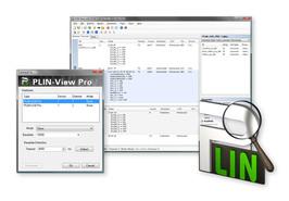
The LIN monitor
PLIN-View Pro for Windows� is supplied with every PC LIN interface
from PEAK-System. Incoming LIN
messages can be viewed using this software, with the use of LDF files
(LIN Description File) allowing the symbolic depiction of LIN
messages. Outgoing LIN frames can be
defined depending on the master or slave operation mode.
PLIN-View Pro also accesses the LIN functionality of the supported
hardware, such as the on-board scheduler or automatic bit rate
detection.
|
|
|
|
|
|
|
|
|
|
| |
|
|
|
|
|
|
|
|
|
|
|
|
Bit Rate
Calculation Tool
|
|
|
|
|
|
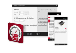
| The Bit Rate
Calculation Tool determines the register values of the CAN controller
for the desired CAN and CAN FD bit rates. Various parameters such as
clock frequencies and sample points can be selected to further narrow
down the list of results. An optional tolerance of up to 5 % can be
defined to include nearby results in the evaluation. The bit timing
values contained in the results (BRP, TSEG1, TSEG2, and SJW) can be
stored and loaded for viewing across platforms. In the Android and iOS
versions, it is also possible to forward the results directly from the
app via e-mail. Furthermore, in the Windows application, individual
lines can be copied from the result list to the clipboard to use their
bitrate values in the PCAN-Basic API and applications based on it. The
transmission rate calculation supports engineers in planning and
optimizing classical CAN and modern CAN FD networks. The Bit Rate
Calculation Tool is available free of charge for Android, iOS and
Windows�. |
|
|
|
|
|
|
|
|
|
| |
|
|
|
|
|
|
|
|
| |
|
|
|
PCAN-MicroMod
Configuration
|
|
|
|
|
|
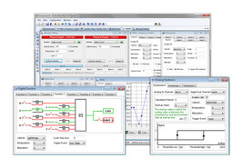
The
PCAN-MicroMod Configuration software can be used to
configure all products based on the PCAN-MicroMod. Specific
configuration options are available for the PCAN-MicroMod itself, the
motherboards, and the Evaluation board, depending on the hardware in
use.
Configuration data is transmitted to the module via CAN.
Use of unique module IDs allows independent configuration of multiple
devices on a single CAN bus.
|
|
|
|
|
|
|
|
|
|
| |
|
|
|
|
|
|
|
|
|
|
|
|
PPCAN-Editor 2
|
|
|
|
|
|
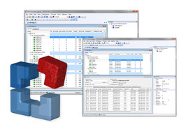
PPCAN-Editor
2 software enables detailed configuration of
various I/O modules with CAN connections, such as PCAN-MIO,
PCAN-Router
Pro, and MU-Thermocouple1 CAN.
This type of configuration process begins with the
definition of incoming and outgoing CAN messages. Then, depending on
the
hardware, the user has a number of different function blocks and other
settings available for processing CAN data traffic. Finally, the
configuration data is transmitted to the module using CAN. This step
requires a PEAK CAN interface.
|
|
|
|
|
|
|
|
|
|
| |
|
|
|
|
|
|
|
|
|
|
|
|
PCAN-Linux
|
|
|
|
|
|
PCAN-Light
for LINUX is the easy to use software interface
for CAN hardware by PEAK-System.
The PCAN drivers for LINUX work with Kernel versions 2.4 up to 4.x The
complete package is distributed under the GPL.
|
|
|
|
|
|
|
|
| |
|
|
|
|
|
|
|
|
|
|
|
|
QNX
Driver
|
|
|
|
|
|
Having
developed QNX driver for PCAN cards, the company
STEINHOFF Automation & Fieldbus-Systems GmbH is in a position to
offer
you these components as a package. The following cards are currently
supported:
PCAN-PCI
PCAN-PC/104-Plus
PCAN-PCI Express
PCAN-miniPCIe
|
|

|
|
|
|
|
|
|
|
| |
|
|
|
|
|
|
|
|
| |
|
|
|
MacCAN
|
|
|
|
|
|
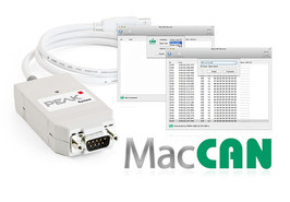
| The PCBUSB
library from UV Software realizes a “PCAN-USB
Driver” for OS X using Apple�s IOUSBKit. The API comes with an
Objective-C wrapper and the software MacCAN, that demonstrates the
functionality of the library. |
|
|
|
|
|
|
|
|
|
| |
|
|
|
|
|
|
|
|
|
|
|
|
CAN
Bus Extension for impulse
|
|
|
|
|
|
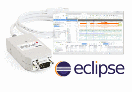
The German
company toem GmbH, located in Solingen, has
developed an extension for CAN, CAN FD, and SocketCAN for its Eclipse
plugin impulse. Based on the integration of the PCAN-Basic API, all
interfaces from PEAK-System are supported. Thanks to the impulse
CANBus
Extension, software developers can evaluate, display, and process CAN
data from one or more CAN and CAN FD buses simultaneously within the
Eclipse environment. Concretely, incoming and outgoing CAN messages
can
be displayed as analog and digital signals, value tables and diagrams.
In addition, message content such as bits, integers, and texts can be
extracted and recorded.
Furthermore, the creation of symbols or the import from
symbol files of versions 5 and 6 is possible. Besides the
determination
of variables and filters, impulse also offers the possibility of
scripting, for example, to send messages or to handle incoming
messages
in a user-defined way. Linux developers can compile the CAN bus
connectivity themselves if required.
|
|
|
|
|
|
|
|
|
|
| |
|
|
|
|
|
|
|
|
|
|
|
|
MathWorks
|
|
|
|
|
|
| Use
PEAK-System CAN devices to stream CAN bus data into MATLAB and
Simulink. |
|
|
|
|
|
|
|
| |
|
|
|
|
|
|
|
|
|
|
|
|
PCAN-FMS
Simulator 2
|
|
|
|
|
|
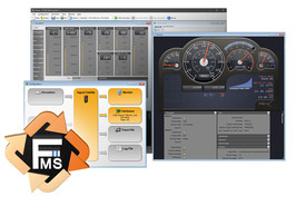
The
protocols FMS (Fleet Management System) and Bus-FMS provide a
manufacturer-independent interface for reading vehicle-specific CAN
data
on heavy commercial vehicles and busses. The extensive and continually
growing support of leading commercial vehicle and bus manufacturers
allows cross-market telematics applications to be implemented.
For these types of developments, the PCAN-FMS Simulator 2 application
made by PEAK-System provides the simulation of both standards in a
single software application with an easy-to-use graphical user
interface.
|
|
|
|
|
|
|
|
|
|
| |
|
|
|
|
|
|
|
|
|
|
|
|
PCAN-Trace
|
|
|
|
|
|
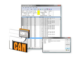
The
PCAN-Trace program is a data logger for up to 9,999,000
CAN messages. It enables CAN messages to be quickly recorded, saved,
and
even played back on the CAN bus. The program displays the number of
received messages and identifies the types of the messages (data
frame,
error frame, RTR frame).
CAN messages can be recorded or replayed in linear or ring buffer
mode.
PCAN-Trace also provides an option to play back CAN messages in single
step mode. You can also simplify analysis and tracing by setting
playback mode breakpoints.
|
|
|
|
|
|
|
|
|
|
| |
|
|
|
|
|
|
|
|
|
|
|
|
PCAN-Symbol
Editor 3
|
|
|
|
|
|
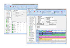
The symbol
format developed by PEAK-System translates the
hexadecimal display used for CAN data traffic into a format that the
user can understand.
To create a symbol, names are first assigned to the
individual CAN IDs. The interpretation and presentation of CAN data is
defined using variables with various parameters, such as name and
output
format. The symbol created in this manner enables easy allocation of
incoming and outgoing CAN messages and ensures that the CAN data is
readable.
The free PCAN-Symbol Editor uses clearly structured menus
and a graphical representation of symbols to enable convenient
creation
and editing of symbol files.
|
|
|
|
|
|
|
|
|
|
| |
|
|
|
|
|
|
|
|
|
|
|
|
PCAN-Symbol
Editor 6
|
|
|
|
|
|
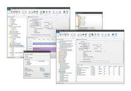
The symbol
format developed by PEAK-System translates the
hexadecimal display used for CAN data traffic into a format that the
user can understand.
To create a symbol, names are first assigned to the
individual CAN IDs. The interpretation and presentation of CAN data is
defined using variables with various parameters, such as name and
output
format. The symbol created in this manner enables easy allocation of
incoming and outgoing CAN messages and ensures that the CAN data is
readable.
The free PCAN-Symbol Editor uses clearly structured menus
and a graphical representation of symbols to enable convenient
creation
and editing of Symbol files.
|
|
|
|
|
|
|
|
|
|
| |
|
|
| |
|
|
|
|
|
|
|
|
|
PCAN-Explorer
|
|
| |
|
|
|
PCAN-Explorer 6
|
|
|
|
|
|
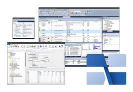
The
PCAN-Explorer 6 is a versatile, professional program for working
with CAN and CAN FD networks. The user is not just limited to the
observation of the CAN traffic. Manual or periodic transmission of
messages or entire transmission lists allows him a direct influence,
for
example, for control purposes or simulations.
The PCAN-Explorer 6 can connect to several CAN and CAN FD busses at
the
same time. Unlike previous versions, the hardware type of used CAN
adapters is no longer a limiting factor.
|
|
|
|
|
|
|
|
|
|
| |
|
|
| |
|
|
|
|
|
|
|
|
|
PCAN-Explorer
6: Plotter Add-in 6
|
|
|
|
|
|
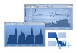
The Plotter
Add-in allows the recording and graphical
representation of any number of signal courses. Signal sources can be
the data from incoming and outgoing CAN messages as well as virtual
variables and results from macro calculations.
Plot Viewer: The free Windows� software Plot Viewer enables the
display
of the records without an installation of PCAN-Explorer.
|
|
|
|
|
|
|
|
|
|
| |
|
|
| |
|
|
|
|
|
|
|
|
|
PCAN-Explorer
6: Instruments Panel Add-in 6
|
|
|
|
|
|
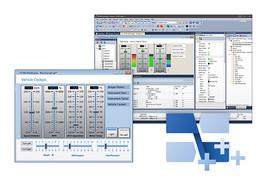
| The
Instruments Panel Add-in allows the graphical
representation of digital and analog signals using different display
instruments. The integrated input options and controllers make it
possible to also generate signals on the CAN bus, allowing easy
simulation of complex CAN applications. |
|
|
|
|
|
|
|
|
|
| |
|
|
| |
|
|
|
|
|
|
|
|
|
PCAN-Explorer
6: CANdb Import Add-in 6
|
|
|
|
|
|
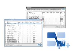
The CANdb
format is a common data description format for
CAN bus information in the car industry.
CANdb Import allows the import of CANdb files. This is a useful
function
for all those who do not want to manually transcribe their database
into
the PCAN-Explorer symbol format.
|
|
|
|
|
|
|
|
|
|
| |
|
|
| |
|
|
|
|
|
|
|
|
|
PCAN-Explorer 6:
J1939 Add-in 6
|
|
|
|
|
|
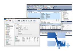
The SAE
J1939 network protocol describes communication on a
CAN bus in utility vehicles for the transmission of diagnostics data
and
control information. It contains a complete network definition using
29-bit CAN IDs (CAN 2.0B Extended Frame).
The J1939 Add-in for PCAN-Explorer supports all definitions
established
by the standard’s parameter groups and provides a simple means
of
accessing the parameters. A database with all the definitions and
parameters contained is also supplied.
|
|
|
|
|
|
|
|
|
|
| |
|
|
| |
|
|
|
|
|
|
|
|
|
PCAN-Explorer
5
|
|
|
|
|
|
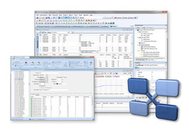
| PCAN-Explorer is a
universal tool for monitoring data traffic on a CAN network. For easy
and clear allocation of the individual messages, these can be
identified
as so-called symbols. The integrated VBScript support allows the
creation of macros to automate complex tasks. The integrated data
logger
means that the data traffic of a bus can be recorded, analyzed, and
stored. PCAN-Explorer is designed as automation server and can
therefore
be remote controlled through scripts. |
|
|
|
|
|
|
|
|
|
| |
|
|
| |
|
|
|
|
|
|
|
|
|
PCAN-Explorer
5: Plotter Add-in 2
|
|
|
|
|
|
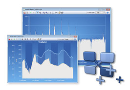
| The Plotter add-in
allows the recording and graphical representation of any number of
signal sequences. Signal sources can be the data from incoming and
outgoing CAN messages as well as virtual variables and results from
macro calculations.
Plot Viewer: The free Windows� software Plot
Viewer enables the display of the records without an installation of
PCAN-Explorer.
|
|
|
|
|
|
|
|
|
|
| |
|
|
| |
|
|
|
|
|
|
|
|
|
PCAN-Explorer
5: Instruments Panel Add-in 3
|
|
|
|
|
|
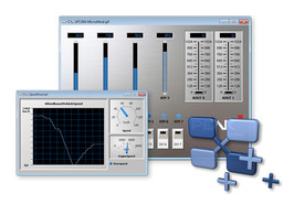
| The Instruments
Panel add-in allows the graphic representation of digital and analog
signals using different display instruments. The integrated enter
options and controllers mean that signals can also be produced on the
CAN-bus, allowing easy simulation of complex CAN applications. |
|
|
|
|
|
|
|
|
|
| |
|
|
| |
|
|
|
|
|
|
|
|
|
PCAN-Explorer
5: CANdb Import Add-in 3
|
|
|
|
|
|
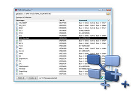
The CANdb format is
a common data description format for CAN-bus information in the car
industry.
CANdb Import allows the import of CANdb files. This is a useful
function
for all those who do not want to manually transcribe their database
into
the PCAN-Explorer symbol format.
|
|
|
|
|
|
|
|
|
|
| |
|
|
| |
|
|
|
|
|
|
|
|
|
PCAN-Explorer 5:
J1939 Add-in
|
|
|
|
|
|
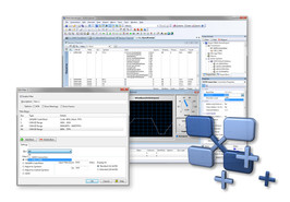
The SAE J1939
network protocol describes communication on a CAN bus in utility
vehicles for the transmission of diagnostics data and control
information. It contains a complete network definition using 29-bit
CAN-IDs (CAN 2.0B Extended Frame).
The J1939 add-in for PCAN-Explorer 5 supports all definitions
established by the standard’s parameter groups and provides a
simple
means of accessing the parameters. A complete database of all the
definitions and the parameters contained is also supplied.
|
|
|
|
|
|
|
|
|
|
| |
|
|
| |
|
|
|
|
|
|
|
|
|
CANopen
|
|
| |
|
|
|
CANopen Magic
|
|
|
|
|
|
| CANopen
Magic is a software to configure, monitor, analyze,
and simulate CANopen and CANopen FD devices and networks. CANopen
Magic
is available in the versions Professional and Ultimate. |
|
|
|
|
|
|
|
|
|
| |
|
|
|
|
|
|
|
|
| |
|
|
|
CANopen Magic Pro DLL - The CANopen PC Developer's Kit
|
|
|
|
|
|
The software
development kit CANopen Magic Pro DLL offers
the functionalities of CANopen Magic as DLL. Custom CANopen and
CANopen
FD PC applications can be developed using this kit. It consists of a
professional CANopen DLL and the PCAN-API from PCAN Developer 3,
together with documentation as well as C header files, libraries, and
import files for popular PC development environments. The CANopen DLL
implements the CANopen� functionality of CANopen Magic. The PCAN-API
is
used to communicate with the connected PCAN interface.
The system is usable for the development of custom analysis
or test applications as often used in production fields or for on-site
service and maintenance.
|
|
|
|
|
|
|
|
|
|
| |
|
|
|
|
|
|
|
|
| |
|
|
|
Embedded
CANopen Library
|
|
|
|
|
|
Various
CANopen solutions are available for our hardware
products. Software libraries or source code based on the Micro CANopen
implementation of Embedded Systems Academy can be used to implement
custom CANopen device or manager applications for our hardware
devices.
The CANopen device configuration is based on CANopen EDS files
(Electronic Data Sheet). The provided EDS editor CANopen Architect
allows the export of configurations that can be imported by Micro
CANopen implementations.
|
|

|
|
|
|
|
|
|
|
| |
|
|
|
|
|
|
|
|
|
|
|
|
CANopen
Controller Library
|
|
|
|
|
|
The CANopen
Controller Library (CANopenIA-MGR) by EmSA
implements a self-configuring, minimal, easy-to-use CANopen manager
and
master. For a host system, it offers easy and instant access to an
entire CANopen network. The library uses the PCAN-Basic DLL from
PEAK-System and can therefore be used on any Windows system with
installed PCAN drivers.
The operator or programmer needs only minimal CANopen
knowledge. The library auto-scans the network on startup and
self-configures to receive and transmit all relevant communication.
The
API allows to access any parameter of any device on the bus, based on
node ID and Object Dictionary entry. The library then chooses the best
CANopen communication method (PDO or SDO) automatically.
|
|

|
|
|
|
|
|
|
|
| |
|
|
| |
|
|
|
|
|
|
|
|
|
CANEasy and ACT |
|
| |
|
|
|
CANEasy
Standard |
|
|
|
|
|
Item number 1.04.0144.00001
CANEasy Standard is a
Windows-based analysis and test
environment for CAN, CAN (FD),
LIN, XCP/CCP & J1939. The tool
simulates the bus traffic, has a
high degree of automation, can
be easily configured and
extended with the help of
plug-ins. CANEasy can be used
throughout the development
process, from testing to
commissioning.
|
|

|
|
|
|
|
|
|
|
| |
|
|
|
|
|
|
|
|
| |
|
|
|
CANEasy Standard Plus
|
|
|
|
|
|
Item number 1.04.0144.00002
CANEasy is a Windows-based
analysis and test environment
for CAN, CAN (FD), LIN, XCP/CCP,
J1939 & UDS. The tool simulates
the bus traffic, has a high
degree of automation, can be
easily configured and extended
with the help of plug-ins.
CANEasy can be used throughout
the development process, from
testing to commissioning.
|
|

|
|
|
|
|
|
|
|
| |
|
|
|
|
|
|
|
|
| |
|
|
|
CANEasy professional
|
|
|
|
|
|
Item number 1.04.0144.00000
CANEasy is a Windows-based
analysis and test environment
for CAN, CAN (FD), LIN, XCP/CCP,
J1939, UDS and Automotive
Ethernet. The tool simulates the
bus traffic, has a high degree
of automation, can be easily
configured and extended with the
help of plug-ins. CANEasy can be
used throughout the development
process, from testing to
commissioning.
|
|

|
|
|
|
|
|
|
|
| |
|
|
|
|
|
|
|
|
|
|
|
|
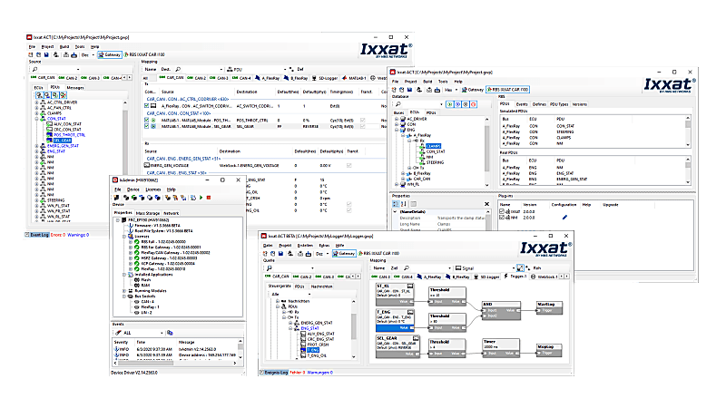
Advanced Configuration Tool Standard |
|
|
|
|
|
Item number 1.12.0248.00001
The Advanced Configuration
Tool (ACT) is a powerful and
easy to use PC software package
for Windows versions 10 and 11.
The tool is used to create
configurations for the CANnector
and FRC-EP devices, including
rest bus simulation (RBS)
functionality. After having
created such a configuration, it
is downloaded to the device and
being executed there standalone. |
|
|
|
|
|
|
|
|
 |
|
|
|
|
| |
|
|
|
|
|