| |
|
|
| |
|
|
| |
|
|
|
|
|
|
|
|
|
|
|
|
|
|
|
|
|
|
|
|
|
PC CAN
Hardware |
|
|
|
|
|
PC CAN Diagnostics & Education
|
|
|
|
|
|
PCAN-MiniDiag FD
|
|
|
|
|
|
Compact Diagnostic
Device for CAN and CAN FD Buses
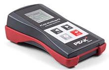
The PCAN-MiniDiag FD is a compact, low-cost handheld device for basic
diagnosis and checking of CAN and CAN FD buses.Service technicians and
developers can easily access networks of vehicles, machines, or
industrial equipment whose configuration is unknown. the device has
measuring functions for the termination, bus load, and voltage levels
at
the CAN connector.
Complies with CAN specifications 2.0 A/B and FD and supports CAN FD
support for ISO and Non-ISO standards
The PCAN MininDiag FD comes with D-Sub, 9-pin (in accordance with CiA�
303-1), OLED display with 128 x 128 pixel resolution, power supply via
exchangeable batteries (3 x Micro AAA with 1.2 V or 1.5 V), operation
via membrane keypad with four keys and plastic casing with increased
Ingress Protection IP42.
|
|

|
|
|
|
|
|
|
|
| |
|
|
|
|
|
|
|
|
|
|
|
|
PCAN-Diag FD
|
|
|
|
|
|
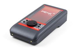
The
PCAN-Diag FD is a handheld device for diagnosis of the
communication on a CAN bus. Possibilities for diagnosis are available
on
the protocol layer by handling CAN 2.0 and CAN FD messages as well as
on
the physical layer by using the oscilloscope function and further
measuring functions for voltage and resistance.
The oscilloscope function is used for a qualitative assessment of the
signal course on the CAN bus. Two independent measuring channels
sample
both lines CAN-High and CAN- Low with up to 100 MHz. Based on the
signal
course, the PCAN-Diag FD decodes CAN frames and shows their elements
in
the scope graphics.
|
|

|
|
|
|
|
|
|
|
| |
|
|
| |
|
|
|
|
|
|
|
|
|
PCAN-MiniDisplay
|
|
|
|
|
|
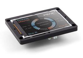
The PCAN-MiniDisplay
is used as a human-machine interface for the
visualization of CAN data. For the connection to the CAN bus, it has
two
High-speed CAN connectors. The graphic representation of incoming CAN
data is configured before using the unit and then is performed on a
TFT
display.
The PCAN-MiniDisplay can alternatively be used for data logging. The
data traffic is recorded to a memory card and can be replayed or
analyzed on a PC later on.
|
|

|
|
|
|
|
|
|
|
| |
|
|
| |
|
|
| |
|
|